- today
- label PUMP OR HYDROPHORE SELECTION
- favorite 3 likes
- remove_red_eye 100170 views
- comment 2 comments
PUMP SELECTION AND CALCULATION OF THE PUMP HYDRAULIC PARAMETERS
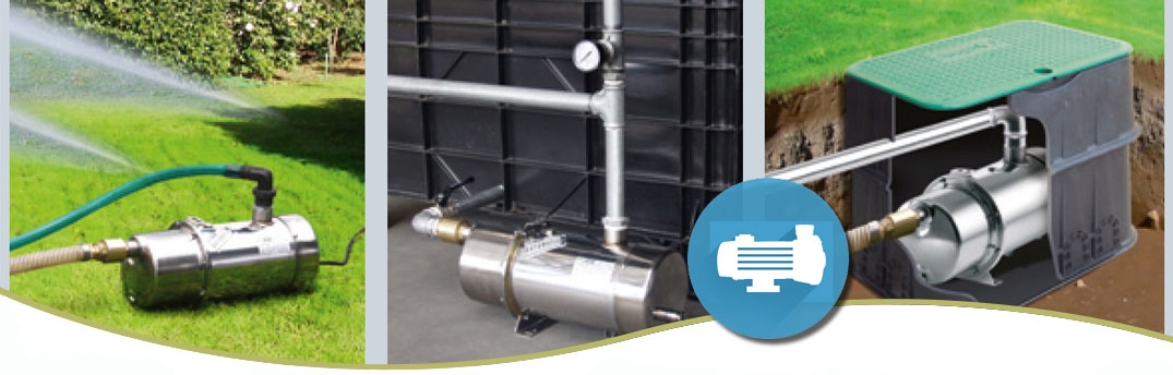
Due to the lack of water supply and sewage systems in many parts of the country, property owners are often forced to build their own water intakes and discharge sewage themselves. It is then very often necessary to use special pumping equipment. There are many solutions of this type available on the market, adapted to the various tasks of the installation.
The nature of the pumped liquid in the system
The first essential question is whether clean water, dirty water or sewage is to be pumped. Pumping clear clean water is much simpler, and most ranges of centrifugal pumps are suitable for this. The task will be performed by both surface and submersible pumps. In the case of polluted water or sewage, it is recommended to use pumps with a Vortex impeller or submersible pumps with a grinder. The crusher is used to grind all permanent elements and fibers present in the pumped liquid.
Selection of pump type and source of consumption
Another important issue in choosing the right pump is determining the source from which the water will be drawn. If water is to be pumped from a surface water intake, surface or submersible pumps are used.
Surface pumps
In turn, surface pumps can be elements of both suction and pressure installations. If the pump is located above the water level, it is a suction pump. On the other hand, pumping of water takes place when the pump is located below the water level in the source (not deeper than 9 m below the pump level).
Submersible pumps
It is worth paying attention to the fact that the submersible pump is equipped with a float to switch it off, which protects it against dry running.
Deep-well pumps
In the case of taking water from a drilled well, where the water table is below 9 m from the level of the pump, it is necessary to use a pump from a series of deep-well pumps.
Determining the "duty point" of the pump
The third step, after the layout of the entire system has been selected, is to determine the pump's "duty point". For this purpose, it is necessary to determine parameters such as the nominal flow Q, i.e. the amount of water pumped per unit time, and the total manometric head Hm. On this basis, you can determine the power consumed by the pump motor.
Determining the manometric height of the lifting Hm
The manometric head is a value based on the sum of the head upwards. This value consists of the geometric height Hg, i.e. the sum of the suction height Ha and the height of the water outflow from the pump Hi, and the losses arising during the flow of water through the installation.
Suction installation with a pump located above the water level in the tank Hg = Hi + Ha
Discharge installation with the pump located below the water level in the tank Hg = Hi - Ha
Determination of the amount of hydraulic losses in the installation
Linear losses due to water flow through the installation are due to frictional forces. The value of the losses is equal to the size of the water column corresponding to the pressure needed to balance them. This value is influenced by factors such as water flow velocity, pipe length and roughness. Local losses are losses resulting from a change in the flow direction or velocity. They consist of all fittings installed on individual sections, such as valves or filters, and couplings, e.g. elbows, tees and reductions. In simplified terms, it is assumed that changing the flow direction by 90 degrees causes an increase in the amount of losses equivalent to the flow of water through a 5 m long section of the installation, and the installation of the valve corresponds to an increase in flow resistance equivalent to a 10 m long pipe section.
Practical calculation example
Table of losses for plastic pipes, e.g. PVC or polyethylene.

Where:
Wewnętrzna średnica rury - Inside diameter of the pipe
Wysokość strat w metrach, przy przepływie poziomym, dla rury o długości 100 m - The loss in meters for a horizontal flow for a 100 m long pipe
Przepływ w l/godz - Flow in l/h
Attention:
For pipes made of other materials (with greater internal surface roughness), the loss resistance will be higher. To determine them, multiply the values in the table by a factor, for example:
1,2 - for vibro concrete pipes,
1.5 - for steel pipes.
Calculation example
Choose a pump for the installation in which we take water from an open tank and force it to the tank located above. The required capacity is 7,000 l/h.
Practical note:
the speed of water in the installation pipes should not exceed 1.5-1.8 m / s.
We can check it according to simple formula:
V = 0,278 Q/S = 0,354 Q/D2
where:
V - flow velocity in m/s,
Q - efficiency in l/h,
S - internal pipe area in mm2,
D - internal diameter of the pipe in mm.
Basic installation data:
geometric height
(suction lift + delivery height): 17 m,
total length of installation pipes: 43 m,
internal diameter of the installation pipes: 38 mm.
Suction Data:
suction height: 2 m,
length of the suction section: 8 m,
number of valves: 1 (non-return),
number of 90 degree elbows: 1.
Pumping data:
pumping height: 15m,
length of discharge section pipes: 35m,
number of 2-port valves: 1,
number of control valves: 1,
number of 90 degree elbows: 2.
Installation calculations:
The amount of losses on the suction side:
Tube length: 8m,
unit losses:
10m (check valve),
5m (90 degree elbow)
equivalent length of the suction pipe: 23 m.
From the attached table, we can read the amount of losses resulting from the water flow of 7000 l / h through a pipe with an internal diameter of 38 mm.
The obtained value is 7.8 m and corresponds to the loss height for a 100 m long pipe.
To calculate it for a 23 m long pipe, divide by 100 and multiply by 23: 7.8 x 23/100 = 1.79 m.
The amount of losses on the discharge side:
tube length: 35 m
unit losses:
10m (globe valve),
10m (ball valve),
10m (2 knees 90ft).
Equivalent discharge pipe length: 65 m
Similarly to the above, we can read from the table the amount of losses resulting from the water flow of 7000 l / h through a 100 m long pipe with an internal diameter of 38 mm. In this case it is 7.8 m. The actual loss for a 65 m long pipe is 7.8 x 65/100 = 5.07m.
Ultimately:
Sum of manometric head = suction head + head + suction head + head loss head = 2 + 15+ 1.79 + 5.07 = 23.86 m.
Based on the obtained results, we know that a properly selected pump should operate at the operating point specified by
capacity: Q = 7000 l/h,
lifting height: Hm = 23.86 m.
The above results are plotted on the pump curve.

The duty point determined by us is between the characteristics of the two pumps. In this case, it is necessary to consider which option will be more suitable for a specific installation. If the user can afford to choose a smaller pump and the slightly lower pump head of 22m, he will benefit economically from lower purchase costs and operating costs related to the electricity consumption of the pump motor. Choosing a larger pump will result in higher expenses, but also a higher pressure (32m). Each case should be considered individually by the user, however in this particular case it would be a wiser decision to choose a smaller pump.
Comments (2)